
From Real ECG to a Virtual Heart: Building an ECG Generator from Scratch
Introduction
In mid-2024, the idea of developing an ECG signal generator came up at the Laboratory. Eduardo Filomena, one of the Laboratory’s members, proposed it with a clear goal: to have a tool that could test electrocardiography equipment while also serving educational and demonstration purposes.
By that time, we had already been working for a while on a 12-lead wireless electrocardiograph. As part of that work, we needed to test the device and, until then, we usually used a function generator that included some biological signals. The problem was that this equipment was limited to a single ECG channel.
A generator capable of producing multiple leads and allowing us to customize the generated signals was especially appealing. It would let us run more complete tests on the electrocardiograph, generate different conditions and signals to evaluate its behavior, and potentially automate test sessions.
That need gave rise to the project documented in this series of posts. We intend to retrace the path we followed during development: from recreating the original design, started by Eduardo Filomena, through the tests and problems we encountered, to the changes and improvements we eventually incorporated.
The starting point was a Raspberry Pi Pico (RP2040) programmed in Arduino. The microcontroller stored the signal data and used it to generate the signals for the 10 conventional ECG leads through PWM. Since the microcontroller’s output was a PWM signal, it had to be conditioned to obtain an analog signal. The outputs passed through a series of passive low-pass filters, which attenuated the PWM’s high-frequency component and reconstructed the ECG waveform. A resistive divider then attenuated the amplitude to millivolt levels.
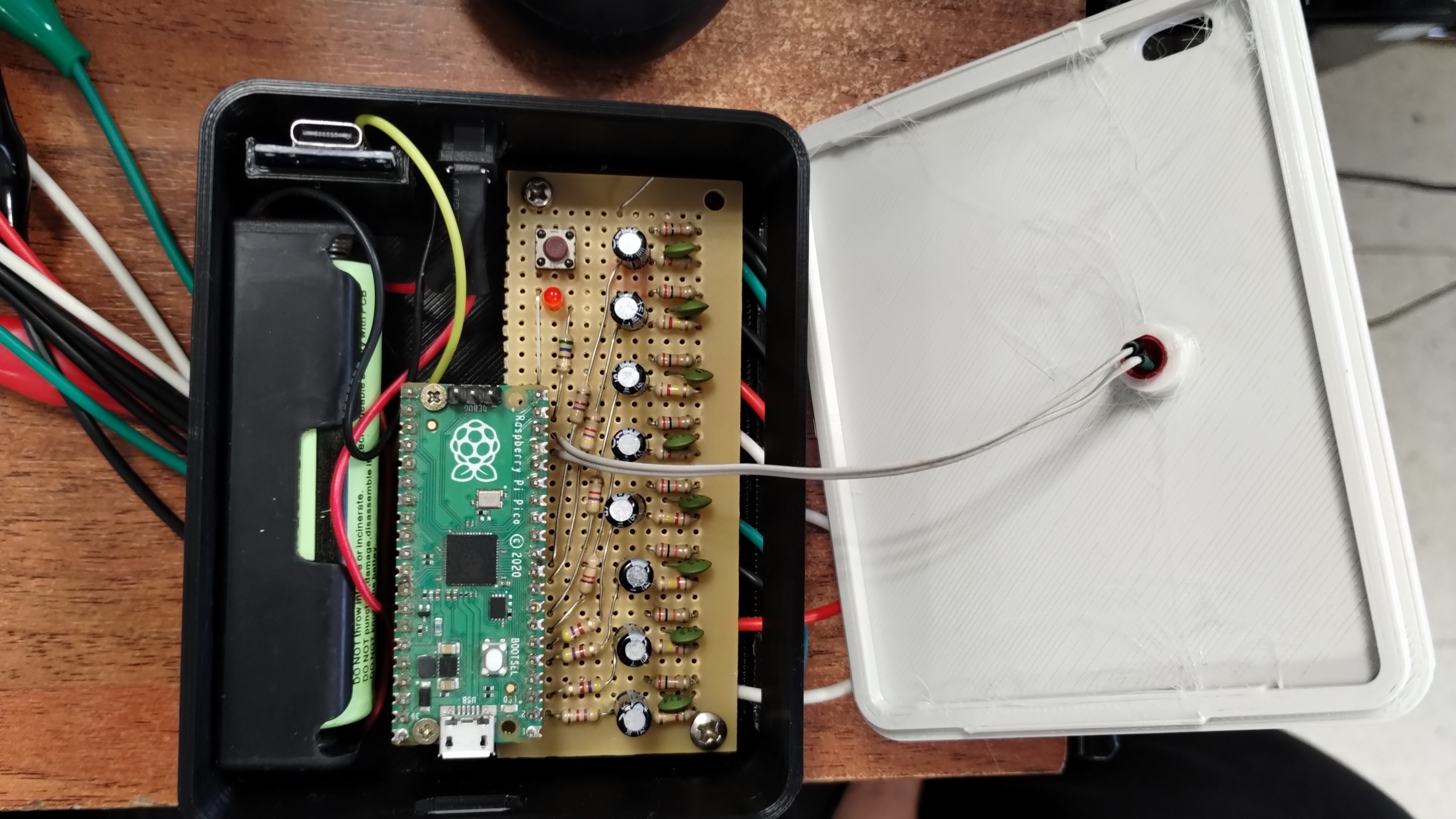
Our first step was to recreate the device. Before modifying it or thinking about a new version, we wanted to understand how it was built, how the signals were generated, and, above all, check how well it worked in practice.
That first prototype proved useful for the initial signal-acquisition tests with the electrocardiograph prototype we were developing.
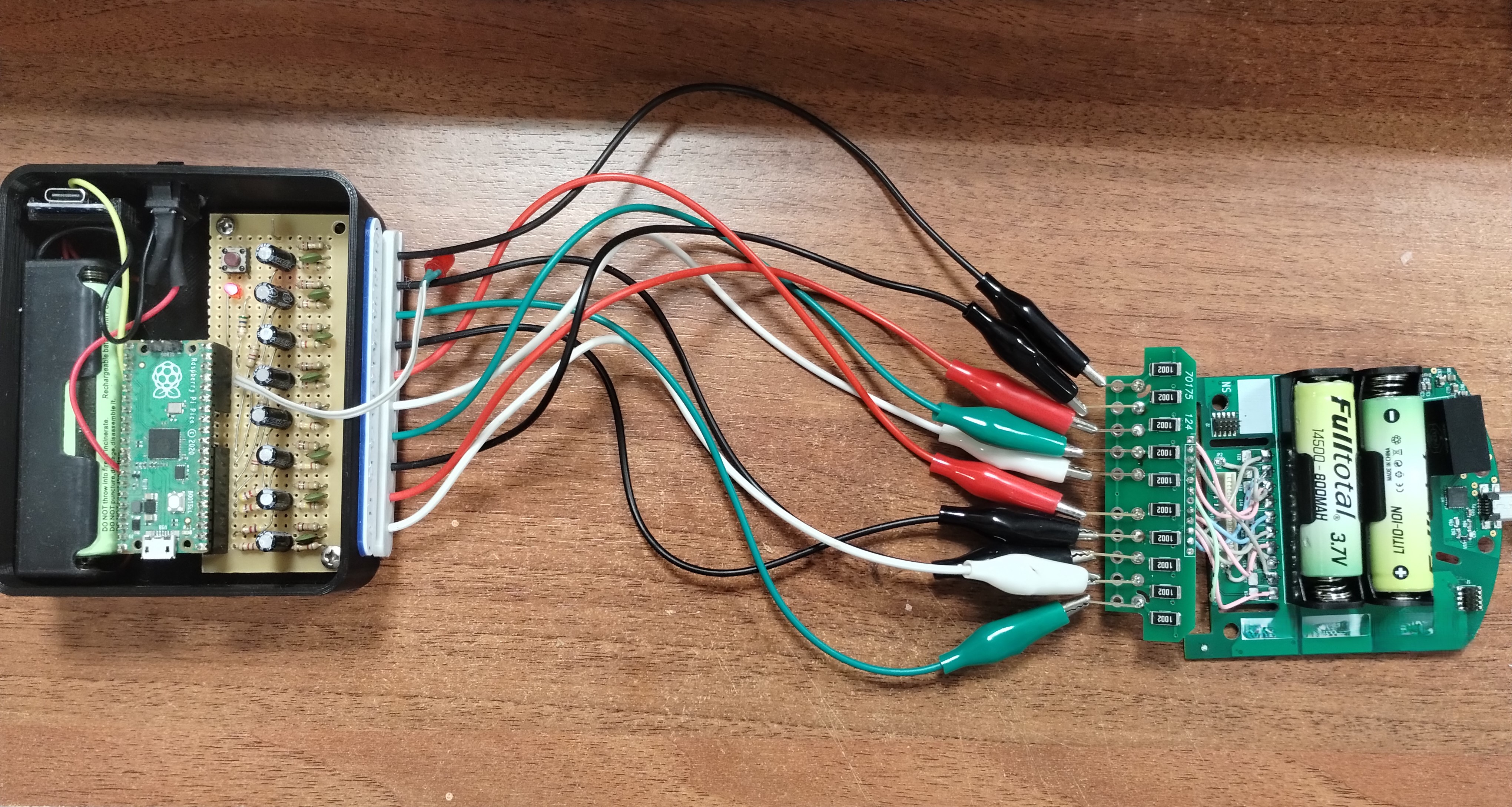
Immediately after recreating the original device, we began improving its capabilities. One of the first changes was migrating the code to C. From then on, we carried out all subsequent development in Visual Studio Code using the official Raspberry Pi SDK for the Pico. As is increasingly common in our projects, various artificial intelligence tools assisted a significant part of the development and programming work.
But we did not want to stop at a software improvement. As we began using the generator, new needs emerged.
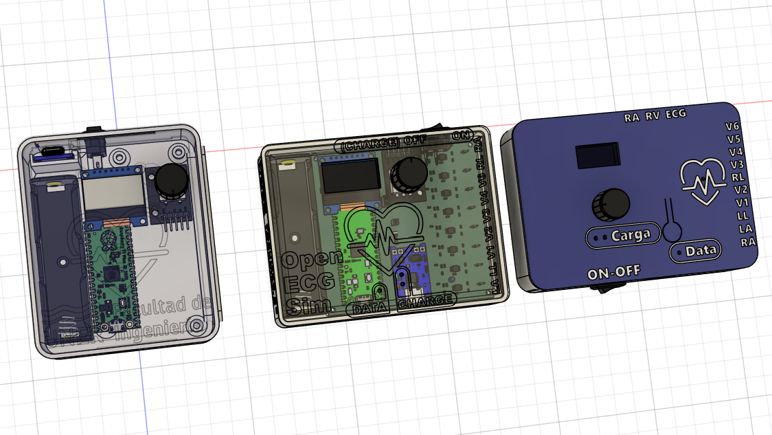
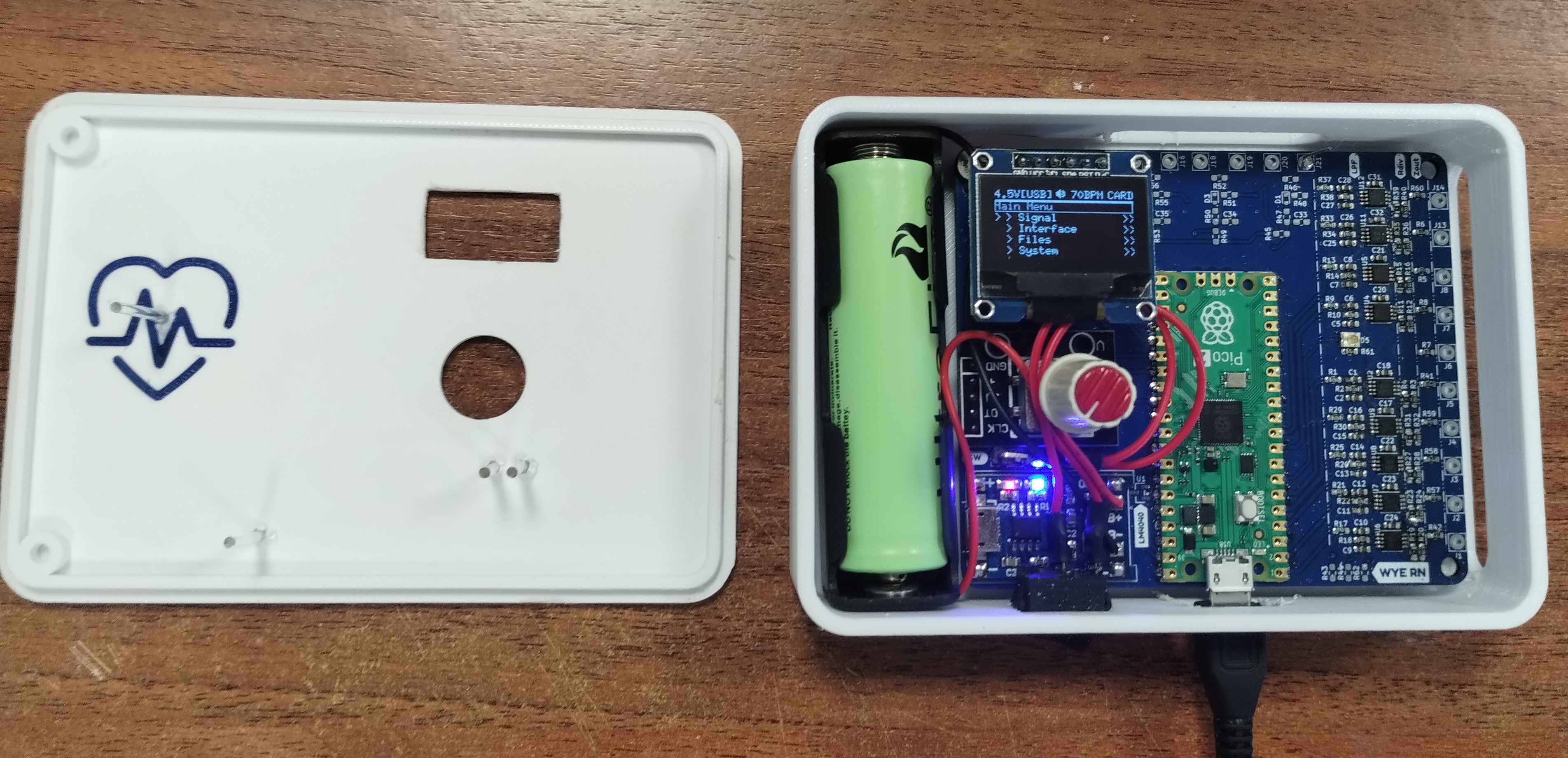
We thought it would be much more useful to have a device that could be carried easily and used independently, without relying on a computer during tests. So we decided to add an 18650 LiPo battery as a power source, along with a charging-management board. Besides making it portable, this offered another benefit for our use case: it allowed us to work with a floating ground reference relative to other equipment during testing.
We also added our own user interface, based on an OLED display and a rotary encoder. This let us select signals and configure the generator directly on the device, without connecting it to a PC.
We developed the enclosure in Fusion 360, going through several versions.
Electronic Design
The circuit design also went through several stages. As development progressed and we gained a better understanding of what we needed from the device, we changed both the electronics and the signal-conditioning approach. First, we switched to a Raspberry Pi Pico 2 (RP2350) to improve the device’s performance. Although the microcontroller was not the system’s bottleneck, it gave us more memory and a faster processor.
The final implementation uses active low-pass filters, specifically Sallen–Key filters, designed to reconstruct analog signals from the Raspberry Pi Pico’s PWM outputs. The design was heavily influenced by the components we already had available in the laboratory. The op-amps are Texas Instruments OPA2335, whose main feature of interest to us was their rail-to-rail operation, meaning they can handle input and output voltages very close to the supply rails. By looking at the passive components we had on hand, we found a combination that gave us a 256 Hz cutoff frequency, appropriate for the application.
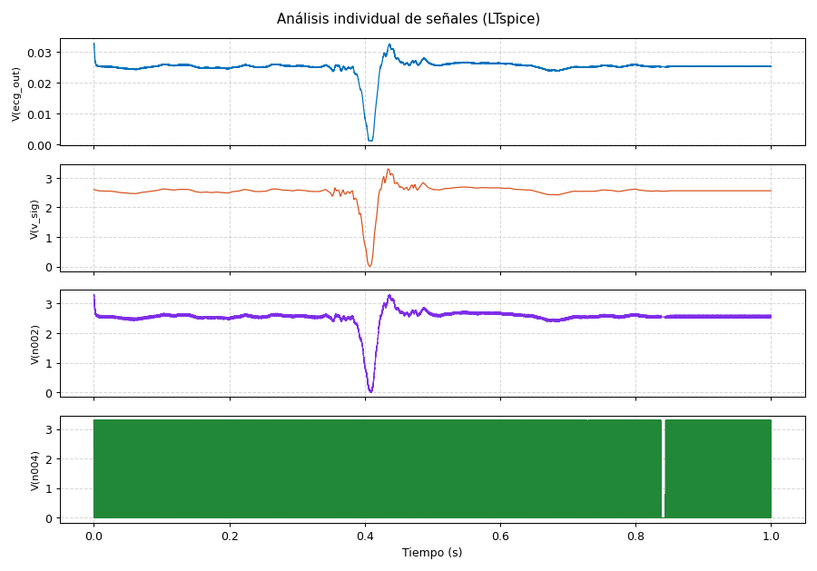
Before building the circuit on a board, we ran several simulations to check its behavior and adjust the components. This allowed us to evaluate the frequency response, attenuation of the PWM’s high-frequency component, and the resulting output waveform.
Simulation
As shown in the image, we ran the simulation using LTspice, a free electronic-circuit simulator developed by Analog Devices.
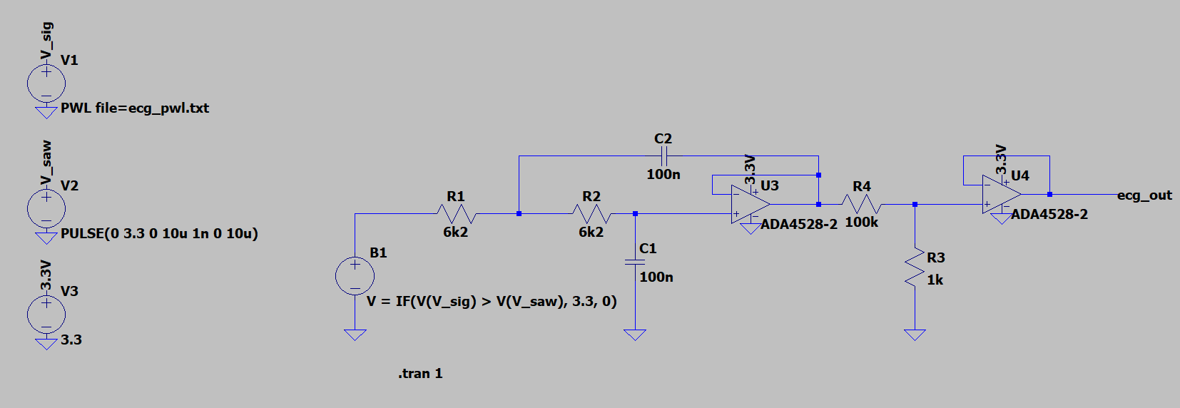
The filter outputs pass through a resistive divider that reduces the signal. A second op-amp, configured as a voltage follower, isolates the divider from a 470-ohm output resistor, intended to simulate tissue impedance.
Around the same time, we were about to start a new project at the Laboratory: developing an external pacemaker. This led us to add a feature that was not necessary for the ECG generator itself but could be very useful in the future. We incorporated three input circuits connected to the Raspberry Pi Pico’s ADC to detect pacemaker pulses.
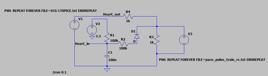
The idea behind this addition was to go beyond simply generating ECG signals. In the future, we wanted to use this hardware as part of a system that could simulate the interaction between a heart and a pacemaker, eventually moving toward an in-silico heart model. At the time, this was still a future idea, but it seemed worthwhile to prepare the platform so the same device could be part of that development.
Signal Generation and Processing
Another improvement we made was to expand the range of signals the device could generate. In addition to ECG signals, we added basic test signals—sine, square, and triangle waves—with controls to change their amplitude, offset, and frequency directly. These signals were especially useful during development because they let us test each stage of the system with known, easily parameterized waveforms. This allowed us to verify PWM generation, filter performance, and output behavior separately before moving on to more complex signals.
The most interesting part, however, came when we started working with real ECG signals. For this, we used the Lobachevsky University Electrocardiography Database (LUDB), which contains 12-lead ECG recordings. We developed a Python notebook to take these recordings and transform them into data that could be used directly by the Raspberry Pi Pico firmware. The first step is to read a recording and obtain its 12 leads. We detect the peaks corresponding to QRS complexes in one of them, then use those peaks as references to identify the cardiac cycles present in the recording.
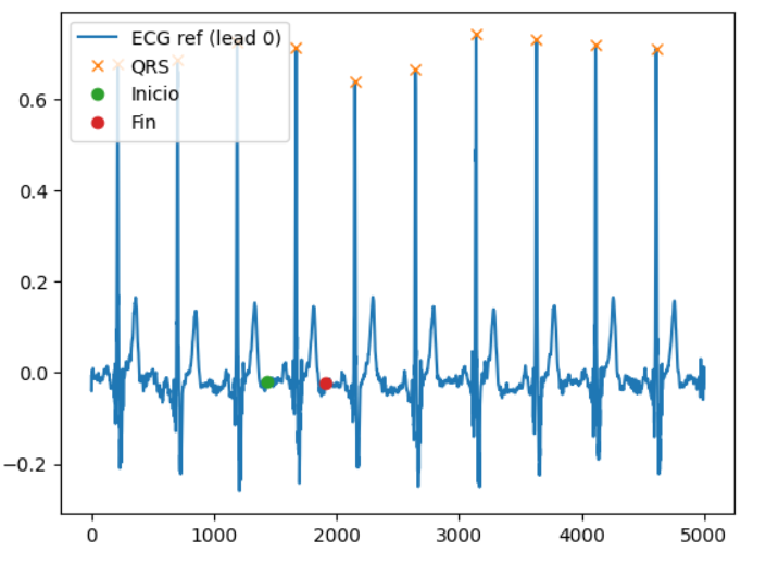
Rather than simply selecting any heartbeat, we looked for one that could be repeated continuously. For each candidate cycle, we calculated the difference between its starting and ending values across all leads and selected the one with the smallest difference. This gives us a heartbeat that transitions as smoothly as possible when it starts again after completing a cycle.
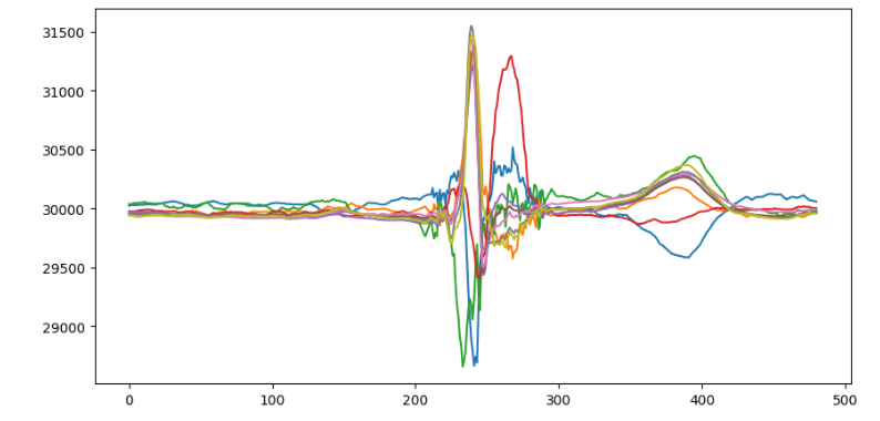
Once a cycle is selected, we extract the samples for the nine leads used by the generator and scale them appropriately for representation as integer values. In our case, the data are rescaled using the operation 2000 + 30000, centering them around the value 30000.
This midpoint offset reflects how the Raspberry Pi Pico works: powered by a single supply (0 V to 3.3 V) and using a 16-bit PWM resolution (0 to 65535), the value 30000 establishes a DC level, or virtual ground, of approximately 1.51 V (45.7% duty cycle). This leaves enough headroom to represent both positive ECG deflections (P, R, and T waves) and negative ones (Q and S waves) without clipping at 0 V.
Finally, all samples are converted to integers and automatically packed into a .h header file. The file contains an array of heartbeat samples along with a structure holding additional recording information, such as rhythm and signal-related characteristics.
The result is a real ECG heartbeat converted into a format the firmware can use directly. The Raspberry Pi Pico does not need to process the original signal or access the database: the samples for the cycle are simply stored in memory and repeatedly played through the PWM outputs.
This processing also gave us something we had wanted from the beginning: the ability to add new signals to the generator without manually changing the firmware. Given a database recording, the notebook selects and prepares the heartbeat and generates the file that we later add to the project.
The generator now has two broad groups of signals: synthetic, parameterizable signals for hardware testing, and real physiological signals, processed and prepared for playback on the device.
Communication and CLI
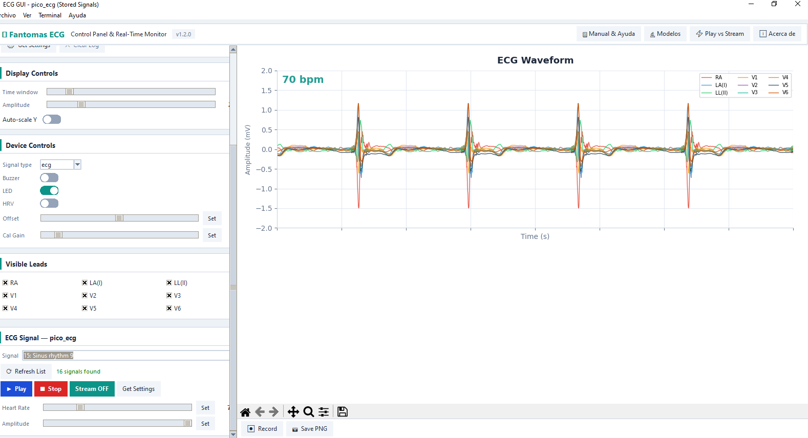
To make testing easier to automate, we also decided to add a CLI to the device, allowing us to change its behavior with commands—for example, the signal type (synthetic or real) and its parameters. We then created a small Python app with a graphical interface to control the device more conveniently. Another important feature of this app is that it lets us view the generated signals in real time. In the future, this could let us compare the generated signal with a hypothetical acquired signal and evaluate the acquisition system’s performance—a way to “close the loop.”
A Limitation and the Next Step
Despite all these improvements, the generator still had an important limitation: the signals it could play were predefined and stored in memory. We could choose among different recordings and play real signals, but we had no easy way to change their morphology or heart rate in real time. This became increasingly apparent as we used the device for testing. If we wanted to change the heart rate, modify a morphological feature, or generate a particular condition, we had to prepare a new signal in advance and add it to the firmware again.
The next question came naturally: could we generate the ECG in real time instead of limiting ourselves to replaying previously stored signals? Starting from this question, in upcoming posts we will explore mathematical models for ECG signal generation. The idea is to move from a system based mainly on replaying stored recordings to one where we can control signal characteristics much more precisely, changing them in real time to suit the test. This opens a new stage of the project: we are no longer only interested in replaying an ECG, but also in understanding how to model and generate one.
There was another limitation, and it was not purely technical. Repeating the same recording indefinitely also meant losing some of the dynamics of a real heart. Every cycle was exactly like the last: the RR interval repeated, the waveform morphology stayed constant, and there was no natural variation in heart rate. There was no baseline drift or small beat-to-beat variation in the amplitude and duration of the different components either. In other words, we could reproduce a particular signal very well, but we were not reproducing the dynamic behavior behind it.
This became especially clear when we thought about what we wanted the generator to do. It was not enough to have an ECG that “looked like” a real recording; we wanted to change its heart rate, introduce variability, alter its morphology, and simulate different conditions without finding and storing a new recording for every case. The first version was still very useful for testing the electronics and verifying real-signal acquisition, but it had a clear limit: we were not simulating a heart; we were replaying a recording of one. That difference is what led us to look for a way to generate ECG signals from a mathematical model.
For now, the files needed to implement this first version of the generator are available on GitHub in the Laboratory repository.
