Portable Algometer
Introduction
Part of the Prototyping Laboratory’s work involves providing technological solutions to other laboratories at the UNER Faculty of Engineering. As part of these activities, we began working some time ago with the Center for Engineering in Rehabilitation and Neuromuscular and Sensory Research (CIRINS), supporting one of its research areas: the study of pain. In the first stage, they asked us to develop an algometer, a device used to measure a patient’s pain threshold. The complete system involved a robotic setup with a linear actuator that applied pressure to the patient’s skin, a force sensor to measure the applied pressure, and a control system for the actuator.
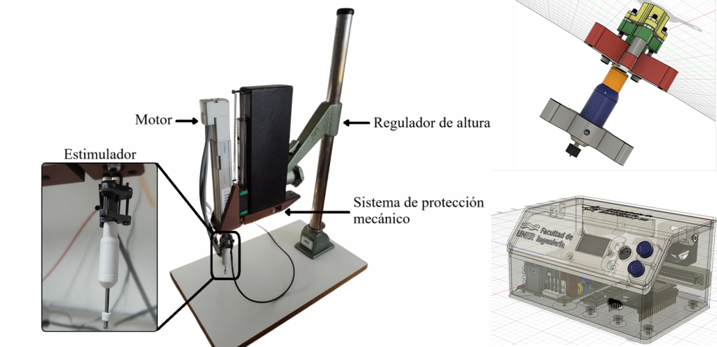
In a second stage, they asked us to develop a handheld algometer that could manually measure a patient’s pain threshold, significantly simplifying the system.
Redesign
The original control system had three power supplies: one for the linear actuator, one for a stepper motor, and one for the control system. For the manual version, we wanted to simplify this arrangement; by reducing the number of components, we were able to power the entire device from a single supply. The original version used an ESP32 DevKit, but it was out of stock when we placed the order, so we chose a FireBeetle 2 ESP32-E. This board includes a LiPo battery charger, which will make it easier to add a battery in the future and make the device fully portable.
The user interface consists of a 128×64-pixel OLED display and a rotary encoder with a push button. We also made the FireBeetle board’s buttons available for quick use. The FireBeetle 2 ESP32-E includes LEDs that we used to indicate the device’s status. The force sensor is the same one used in the original system: Honeywell’s FMAMSDXX005WC2C3. We also added a BNC connector, which can be used as an input with a push button (to indicate external events) or as an output to synchronize with other devices.
CAD Modeling
We based the physical design on the original system, but simplified the structure to make it significantly more compact and lightweight. The overall structure is a stack of 3D-printed parts held together by three M3×35 mm screws. We chose this approach because it allowed us to iterate quickly on individual sections of the design and made it easier to orient the parts for printing.
We placed the sensor in a kind of cradle built into the plastic part that holds it, and soldered the wires directly to its pads, avoiding the need to add a separate PCB.
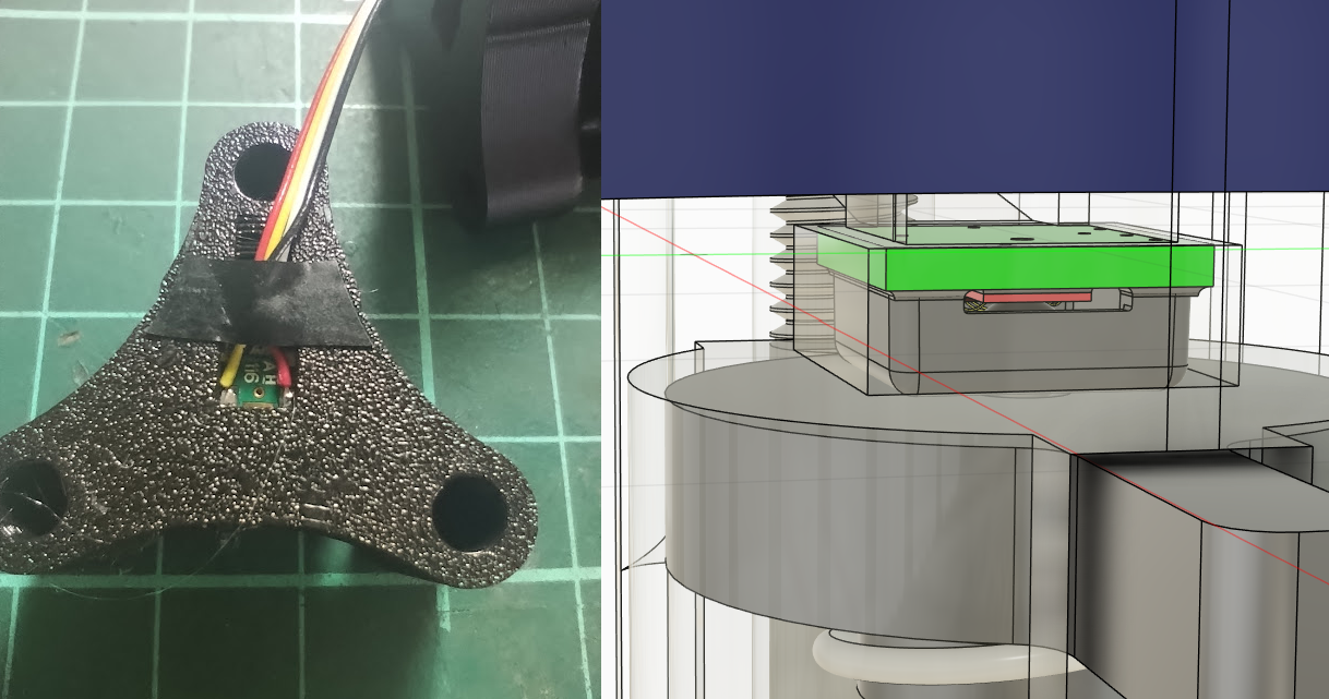
Force is transmitted from the external contact point to the internal sensor by a 2.5 mm diameter steel rod. It slides smoothly inside a bronze sleeve and is supported by a plastic part. A spring applies force to the rod, keeping it in constant contact with the sensor with a preload of approximately 120 grams.
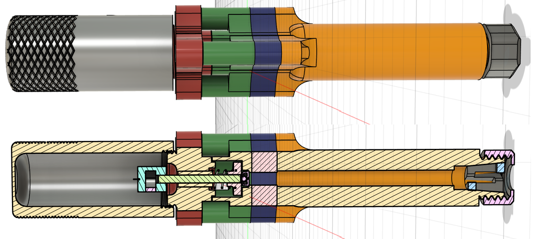
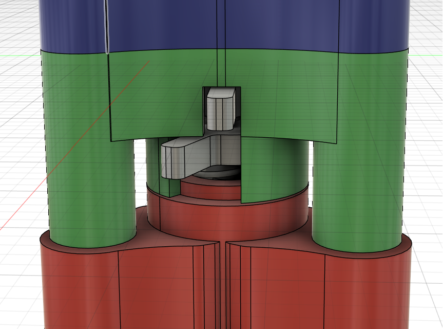
We also designed a small handle on the plastic part that supports the rod. It lets us pull the rod away from the sensor temporarily and lock it in place. This protects the delicate sensor from overload while we change the patient’s stimulation tip, which may be pointed, a blunt blade, or another type.
We also made a cap that attaches to the front to protect both the stimulator and the internal parts during transport. At the back, we added a cable clamp made from a wedge printed in a soft material (TPU) and a quick-threading nut. This allowed us to secure the cable firmly to the device body and prevent it from being pulled out.
Finally, we designed the control-module enclosure as two large interlocking parts joined by three M3 screws.
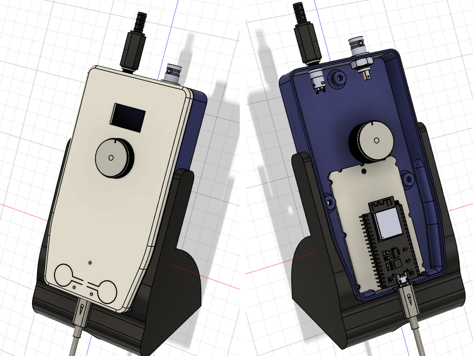
To make the FireBeetle board’s tactile buttons easy to use, we designed and printed small flexible plastic structures that press the on-board buttons when pushed from the outside. We had used similar solutions before, but in this case the FireBeetle buttons were soldered at 90 degrees. This orientation required more careful analysis to ensure the natural rotation of the printed part produced the optimal linear movement to trigger the button’s internal mechanical click without damaging it.
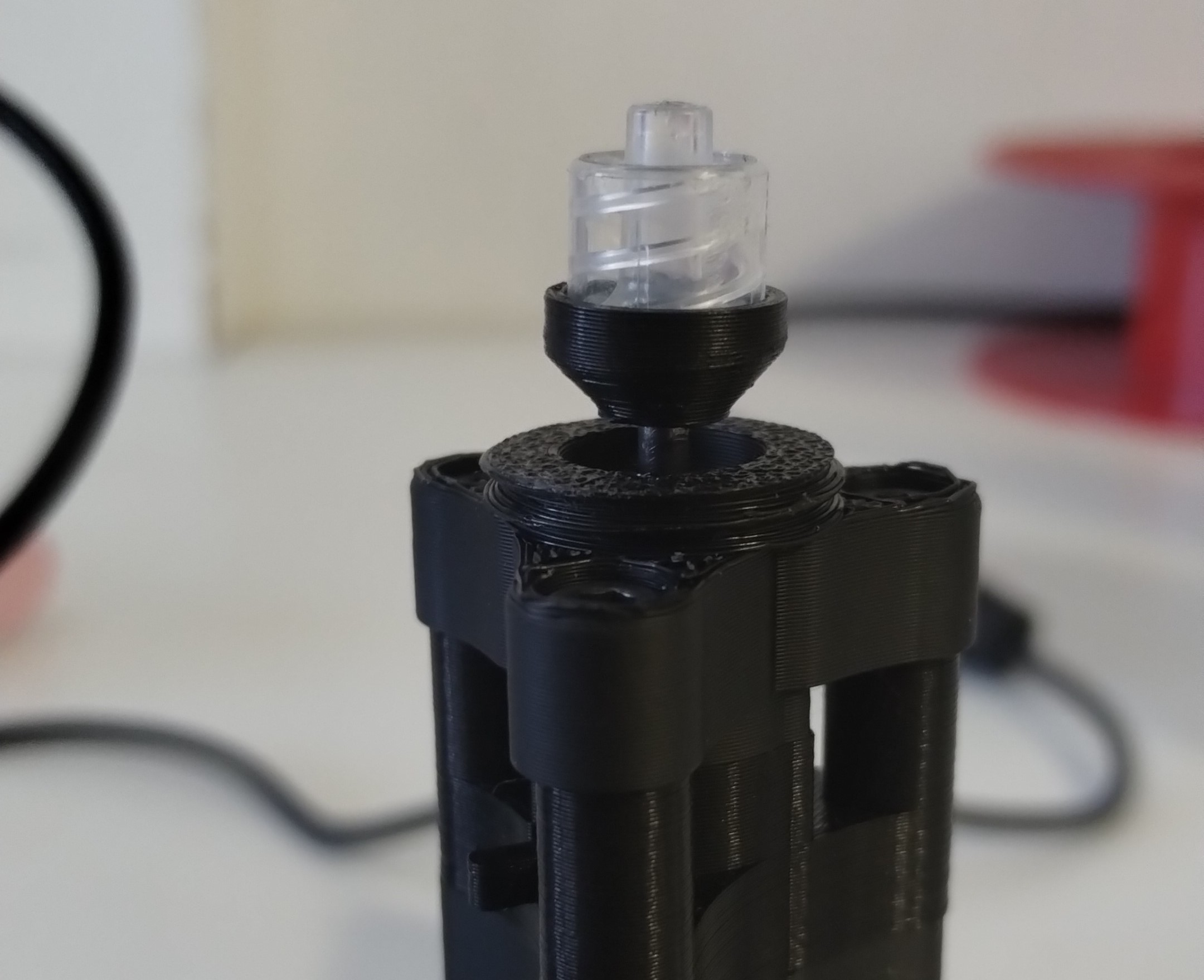
The stimulation tip used in this particular case is a hypodermic needle whose bevel was removed to prevent cuts and skin penetration. We considered printing a Luer-style lock to hold the needle, but the part was too small and complex, so we chose to reuse a plastic lock from a syringe.
Testing
To test the device, we printed additional mounting parts. These let us firmly clamp the stimulator in a vise and place a standard 100-gram weight on the actuator.
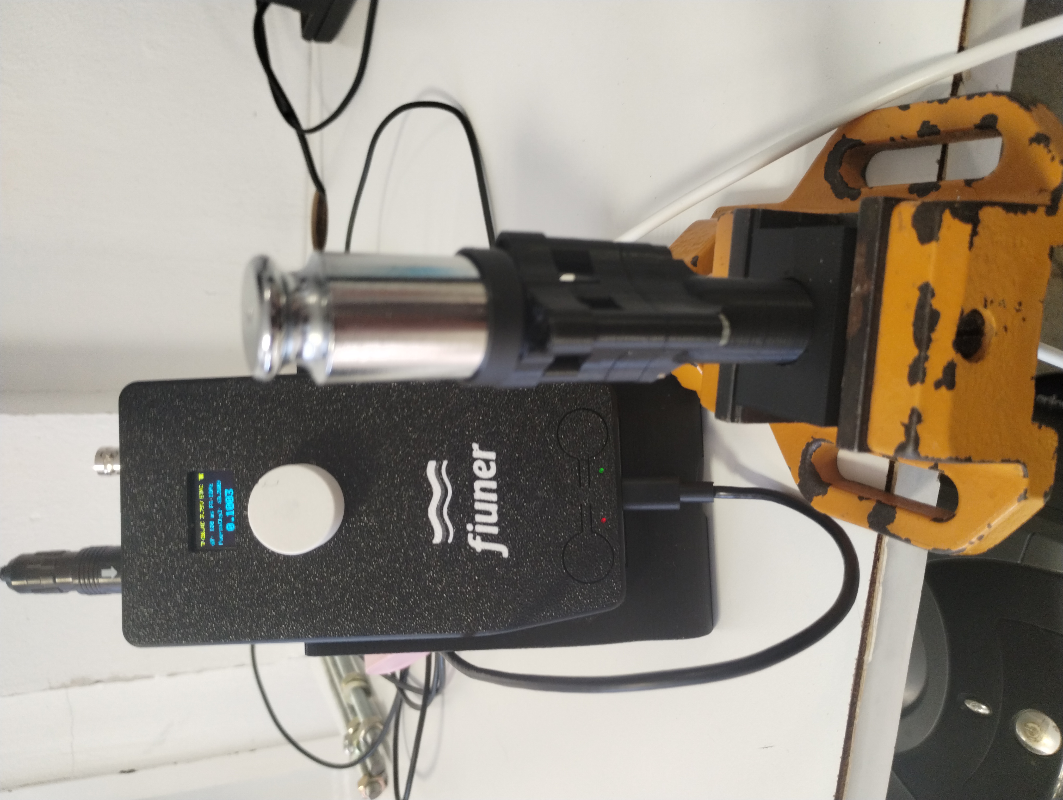
We captured data with no load and with the weight on the sensor, at both 10 Hz (the normal operating frequency with real-time display) and 500 Hz (the maximum frequency during measurements).
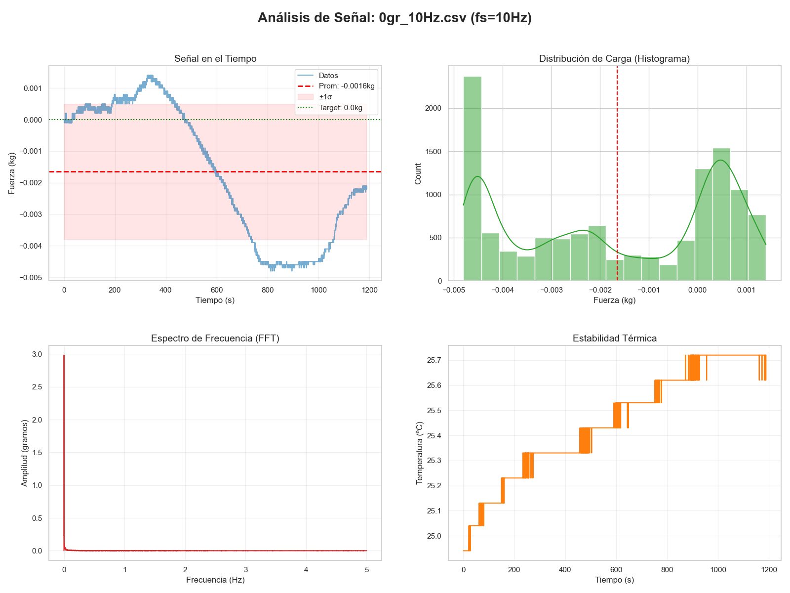
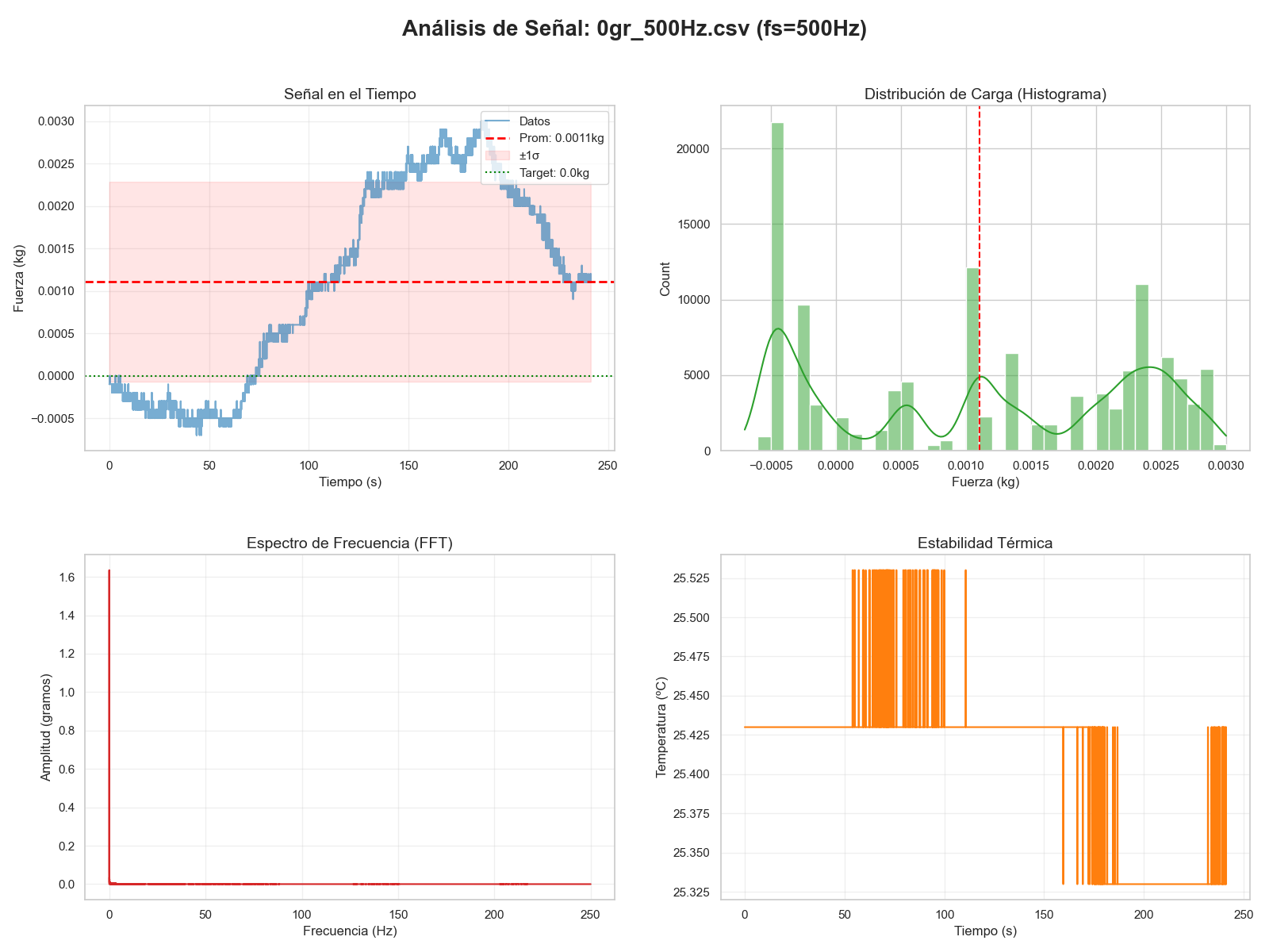
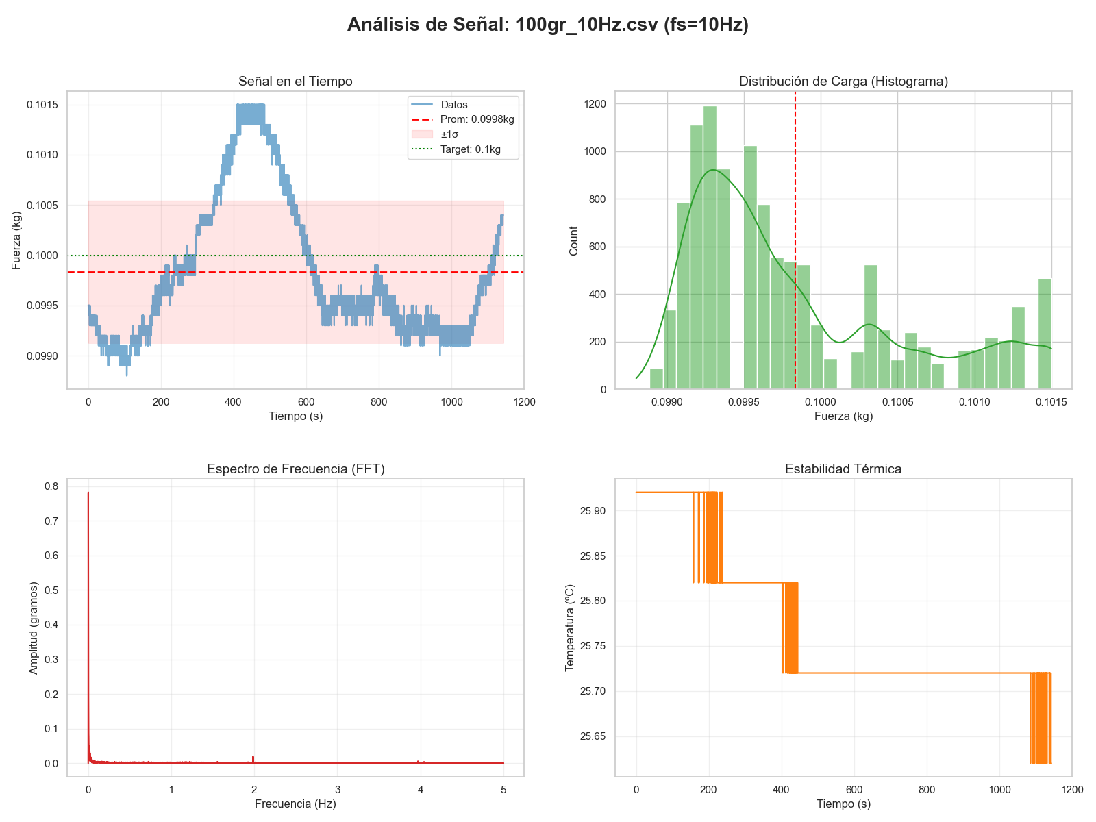
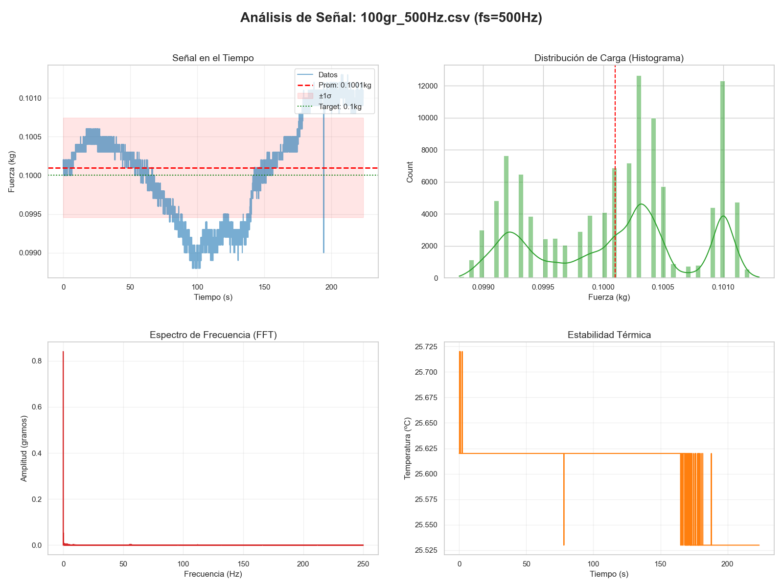
When analyzing the sensor measurements, the first thing we see is that the average values are accurate: when a 100 g load is applied, the system measures very close to that value. However, looking at the signal in detail over long periods reveals small variations and slow drifts. These are not random noise, but effects intrinsic to the sensor, such as temperature changes or internal mechanical settling. This is also visible in the histograms, where the distribution is not perfectly clean, and in the frequency analysis, which shows that nearly all the variation happens very slowly, close to zero Hz.
In actual use, however, things are quite different. If the sensor is zeroed immediately before a measurement and used for only a few seconds, these slow effects are no longer a significant problem. Over that short interval, the system is much more stable, and what dominates is simply a little electrical noise in the signal. In practice, this means the sensor works well for quick measurements as long as it is calibrated beforehand. The reading can be smoothed further by averaging a few values. In short, although it is not ideal for prolonged measurements without recalibration, it is perfectly usable and reliable in short, controlled scenarios, where it performs best.
